
A metal ceiling can look even across the main field while a small gap or uneven return draws attention at the perimeter. Edge trim must fit the specified ceiling system, the wall conditions and the sequence the installer can actually follow. Before folding a batch, assemble a representative section with the real panel edge and the intended perimeter detail. A short trial can reveal where the drawing, folded profile or installation sequence needs another look.
Establish the metal ceiling edge detail
Start with the latest ceiling and perimeter drawings. Identify where each trim section is intended to meet the wall, panel edge and adjacent hardware. Mark which face is visible, which edge is used as the installation reference and where the designed joint or reveal is measured. Record which trim pieces are mirrored or handed so the shop does not produce one orientation for all locations.
Confirm that the metal ceiling mockup uses the specified edge condition and the intended installation sequence. Ask the responsible designer or system supplier which dimensions must be kept when adjusting for field variation. If the drawing and the physical panel differ, resolve the mismatch before using either as the template for a full run.
Include the wall and panel conditions in the mockup
A perfectly straight sample board can conceal how a trim detail will respond to variation at a wall. Use field dimensions to select a representative condition and agree how it will be simulated. Keep the support and the panel orientation close to the installation drawing. Label the reference plane and record how the fixture reproduces the setting that matters to the joint.
Fit a metal ceiling panel edge alongside the trim without forcing it into position. Record the initial reveal and any contact point that keeps the edge from reaching its intended seat. If the joint looks uneven, distinguish the measured trim geometry from the wall or fixture condition. A photo with a visible reference line is more useful than an isolated close-up of a gap.
Fold a trial length of the wall trim
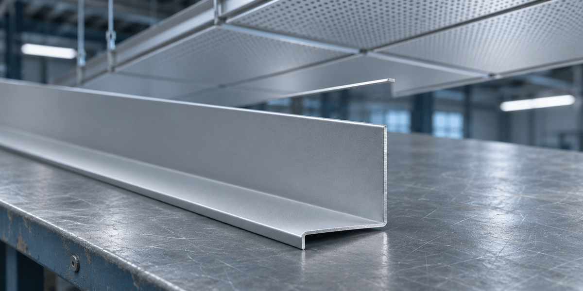
Use the approved cross section to mark the wall leg, visible edge and return on the sample drawing. Confirm which face stays visible after installation. Ask the fabricator to check the bend order against the actual tooling before the trial. A return formed too early can interfere with a later fold. A short sample can establish that the cross section fits, while a longer sample can reveal twist or a change in reveal along the run.
After folding, set the trial length on the drawing references and check the wall leg and return before fitting a ceiling panel. If the trim is reversed or twisted, record that condition while the part is still on the bench. This gives the shop evidence it can compare with the mockup. Fit any ceiling tile from the specified system as a separate component.
Check fastener access and panel removal
Walk the intended installation sequence with the installer. Check whether the selected tool can reach the specified attachment points after the adjacent component is placed. Note any dependency on working from one end or fitting one segment before another. Confirm that the receiving piece has enough clearance for the panel motion shown in the system instructions.
If the metal ceiling detail allows access or panel removal, demonstrate the intended motion in the mockup. Check whether the return, cap or nearby accessory interrupts that movement. A panel that fits in place may still be difficult to remove if its edge must tilt or slide first. Route changes that affect the specified ceiling system to the responsible designer or supplier for review.
Inspect the visible face and the reveal together
Use production material and finish for the trim sample if appearance is part of approval. Mark the visible face before the sample is handled and check the areas contacted by tooling, supports and adjacent components. If the finish uses protective film, note whether it was present during folding and when it was taken off for inspection.
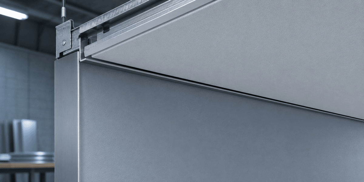
Compare the visible edge of the metal ceiling mockup at the intended viewing angle and under representative lighting. Measure the reveal at more than one station along the edge when practical. Keep the appearance observations and dimensional results in separate fields. For example, a visible shadow can change because of lighting even when the physical joint measures consistently.
Discuss long folds and returns with the equipment supplier
Bring the trim drawing, planned material and a representative blank to the demonstration. Identify which fold produces the visible edge and which bends create returns that might reduce tool clearance. Ask the supplier how the blank is positioned and supported on the proposed machine and what geometry needs to be tested on the actual setup.
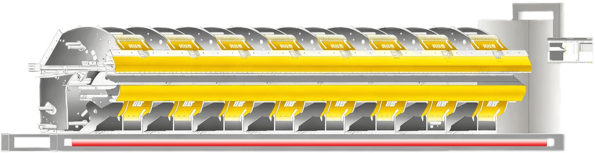
For long metal ceiling perimeter profiles, refer to ARTITECT’s automatic double folding equipment when preparing questions about sheet positioning and fold direction. Ask for a demonstration on the proposed configuration and compare the result with the intended ceiling interface. A successful trim sample can show how that part was formed. It does not qualify the complete ceiling assembly.
Worked example: identify where the reveal changes
Imagine an approved drawing that calls for an even reveal but a mockup shows the gap gradually widening along a metal ceiling edge. Mark several measurement stations. Compare the trim’s returned edge against the drawing before removing it, and record the reference used for each measurement. If the trim is consistent but the mock wall plane varies, send the wall condition and measurements to the detail owner for review.
In a second trial, the reveal might read consistently while the removal motion catches at the returned edge. Record where the two pieces first touch and note the installation step that exposes the issue. The remedy could involve the order of assembly or the detail itself. Record the proposed change, obtain the appropriate approval and repeat the affected check on the revised mockup.
Capture a release record the shop can use
A metal ceiling trim release record should contain the ceiling system reference, drawing revision, visible faces, measured features and approved installation sequence. Include a photo that identifies the joint and another that shows any problem area. Flag open items with an owner and a retest condition. Keep an accepted sample or annotated image available for the production team.
Before folding the batch, check that the shop drawing, material and tooling match the approved sample. If a later change affects a visible bend, attachment point or removal path, identify the affected interface and repeat its mockup check. Document what was verified so a later production team can distinguish approved variations from issues still open.
Questions about metal ceiling edge trim
Can the same trial cover both sides of a room?
Use one trial for locations that share the same detail, panel orientation, attachment and access. A mirrored part or different wall finish can change how the trim meets the panel. Identify the locations covered by the trial on the release record.
Can I use a different finish for the mockup?
A substitute can help check whether parts fit together. Use the actual finish and material before approving surface appearance or handling marks. Label the sample so fit observations are not mistaken for approval of the final surface.
Should a short sample be used to judge straightness?
A short metal ceiling trim sample helps verify the cross section, clearances and attachment sequence. Check a representative longer piece if the finished appearance depends on straightness along the run. Compare it to the project’s agreed reference and tolerances.
Bring your perimeter detail to an equipment discussion
Share the metal ceiling perimeter detail, trim drawing and finish requirements with ARTITECT. Include the longest profile and any return that affects tool clearance or installation access. That gives the team a basis for discussing the folding setup and the sample checks your fabricators and installers need.