
Sheet Metal Bend Radius: How to Specify and Verify It
Sheet Metal Bend Radius: How to Specify and Verify It
A sheet metal bend radius is usually specified at the inside of the formed corner. To choose a useful value, start with what the corner has to fit around or clear. Then confirm that the material and folding setup can make that radius, at the required angle, without damage. The drawing should distinguish a functional radius from a routine forming detail. When the radius is critical, verify it on representative material and check it again on a first-off profile. An accurate radius measurement on a small sample is valuable, but it does not prove that a full-length panel fits its mating parts.
Start with the space around the corner
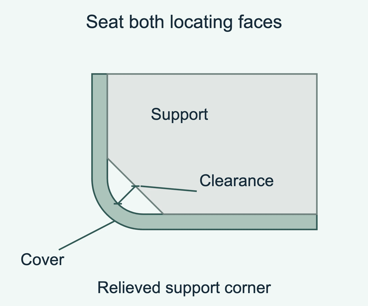
Conceptual section: the straight cover legs contact both support faces. The chamfered support corner leaves clearance to the inside bend; the diagonal gap is illustrative, not a specified tolerance.
Imagine a folded metal cover that has to wrap over a support and sit against two locating surfaces. A sharp-looking corner on the drawing may leave less room than the real part needs. If the inner surface of the corner runs into the support, neither locating face may seat as intended. Conversely, changing to a larger radius to suit fabrication could move the usable straight portions of the legs and affect the position of a nearby hole. The relevant design question is which surface must land where when the cover is installed.
Show the mating section beside the formed part. Identify the surfaces that locate the assembly, the minimum clearance at the corner and any limits on the visible outside shape. If a radius is important only because it must clear another component, confirm whether the actual acceptance requirement is a specified radius, a clearance envelope or both. A shop can measure a clearance against an approved template or mating part. A numerical radius callout needs its own measurement method and acceptance limit.
A panel with an exposed finished corner adds another consideration. The designer may need a consistent visual transition across adjacent parts even when they have generous mechanical clearance. Record this as a separate requirement. A finish sample or a set of adjoining profiles can help establish what is acceptable for the project. Visual agreement should be explicit enough that the designer and shop can tell the difference between a harmless variation and a corner that needs to be remade.
Label the inside radius and angle clearly
On a section view, point the radius callout to the inside surface of the bend. Specify the formed angle and identify the angle convention. A change from the flat condition and the included angle between the legs can be described with different values, so use a section that makes the intended opening clear. Include the material, thickness and relevant finish. If the part is made in left-hand and right-hand versions, identify which face is visible and show the orientation that the inspector will see.
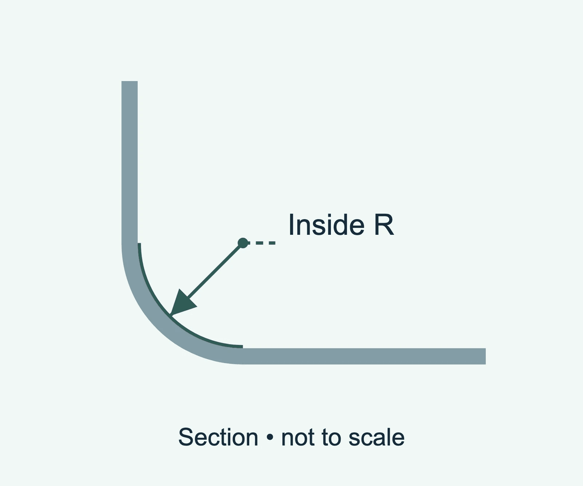
The inside radius is measured on the inner surface of the formed bend. Section not to scale.
Use the same datum surfaces in the design review and the inspection instructions. A leg length measured to the theoretical intersection of two faces is different from the length of the straight section ending at the tangent to a bend. Changing the datum can appear to change the part even when the metal has not moved. If a flange is measured to an outside face on the assembly drawing, show where that face falls in the section rather than relying on the operator to infer it from a flat blank.
Give tolerances to the features that control assembly or appearance. A nominal radius without a tolerance or agreed inspection rule leaves a receiving inspector unsure what to accept. When the precise curvature is less important than fit, discuss whether a clearance check better reflects the function. When several bends carry the same nominal radius, identify any exceptions on the drawing so a fabrication note does not accidentally cover an edge that has a different purpose.
Check the material and proposed folding setup
A minimum bend radius is not a universal number for sheet metal. The allowable geometry depends on material, thickness, condition and forming method. A sample made from a different alloy or temper can make a tight bend look feasible while telling you little about the production stock. Use the specification that actually applies to the order and check supplier guidance for the material. Where rolling direction matters, mark the direction on the blank and relate it to the bend line so the coupon and finished part can be compared.
Confirm the setup with the fabrication team before freezing the drawing. Ask how the part is supported, what tools will contact the metal and how the planned angle will be verified after the bend is released. A control may compensate for springback by commanding a different movement than the final angle suggests. The relevant reading for inspection is the settled part under the agreed measurement condition. Keep the programmed value in the setup record and the observed angle in the inspection record so neither is mistaken for the other.
Consider the practical limits of inspection early. A radius gauge may be suitable for comparing an accessible coupon against known sizes. A protected or crowded finished profile can make it difficult to see whether the gauge fits against the curved surface. If the radius must be demonstrated quantitatively, agree on an appropriate profile measurement method and the accessible locations in advance. Do not infer an exact value from a poor visual fit or from a tool designation alone.
Make a representative coupon and record the result
Use a coupon made from the specified stock with the same thickness and, where relevant, the same orientation and surface condition. Make the sample large enough to hold, fold and inspect using the agreed process. Label it with the material reference, setup and part revision. If a supplier sample arrived without those details, keep it as an illustration and make a separate production-representative sample before relying on the result.
Measure the formed angle after release and check the inside radius independently. Examine the outside surface for cracking and finish damage using the project's approved inspection criteria. Check the locating legs as well. A corner can look smooth and still place the legs at the wrong angle. Likewise, a coupon with legs at the intended angle can have a radius that fails the clearance requirement. Record observations separately so a single pass mark does not hide the reason for acceptance.
If the test fails, isolate the variable you intend to change. For example, if the part has the right angle but interferes with the mating corner, the review should focus on radius, clearance and the agreed datums. If the radius appears acceptable but the angle opens after release, investigate the angle setup and recheck the section after adjusting it. Keep the unsuccessful sample or its measurements until the difference is understood. Changing several conditions at once can give you a better-looking part without revealing which change helped.
Confirm the bend on the full-length first-off
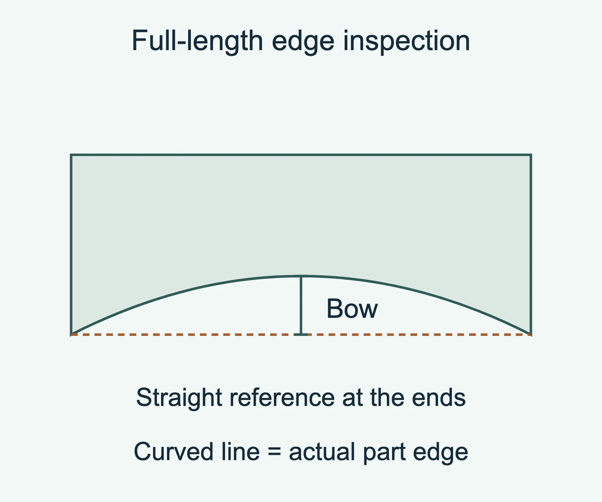
Illustrative edge bow, exaggerated for clarity. Compare the actual full-length edge with a straight reference under agreed support conditions; the diagram is not a measured part.
Repeat the relevant checks on a first-off panel at the intended length. A short coupon is useful because it isolates a bend. A long part introduces support and handling conditions, and a multi-bend profile adds tool access constraints that the coupon does not represent. Check at the locations agreed for the part, including the ends and representative intermediate positions if the radius or straightness is critical along the length. Avoid holding the part in a way that forces it into the nominal shape during inspection.
Make a trial assembly using the real mating pieces or an approved fixture if the radius controls fit. Place the part against the designated locating faces and confirm that the corner clears the support without prying or forcing. On a visible architectural assembly, inspect the finish and adjacent seam under the conditions agreed for acceptance. Record the panel orientation and the method used so the shop can repeat the result after a change in batch or tooling.
If the formed profile satisfies fit but differs from the drawing, route that difference through the project approval process before releasing the run. If a change is authorized, revise the drawing and inspection notes together. Updating only the machine program would leave the next operator working from a different target. Where the CAD model uses an unfolding table, keep its revision with the validated setup. Autodesk’s bend table documentation describes how material thickness, angle and radius are represented in that workflow. The model should reflect the assumptions the team has actually checked.
Preserve the identity of the accepted sample where the setup will be used again. Attach its measurements and inspection method to the drawing revision. If the purchasing team later approves a substitute material, use the existing record to decide which checks the change invalidates. The original first-off remains evidence for the configuration it represents. A new lot or tool arrangement can be evaluated against that evidence without guessing what the first team did.
Build a useful package for a folding review
Send the formed cross-section, the material specification, the part length and the intended bend radius along with the tolerances that matter to assembly. Include a photo or drawing of the mating part when the corner is used for clearance. If a coupon has been made, provide the measured angle and radius, the material reference and the setup notes rather than just a photograph. Those details allow a reviewer to distinguish a forming constraint from an inspection ambiguity.
For a project with several part families, identify the features that set the limits. A long panel with a modest radius and a short return may pose a different handling problem than a shorter part with a tight corner. Share both where they affect selection. Explore ARTITECT machine functions for the available folding and handling options, then confirm the configuration against the actual drawing and stock. An approved radius comes from agreement on the design requirement and evidence that the intended production process can achieve it.